思科配置VLAN间单臂路由
为什么要配置单臂路由
路由器上链接不同的VLAN的物理接口数量有限,随着VLAN增加端口很快就被耗尽,然而VLAN中继允许单个路由器物理接口接多个VLAN的流量,即有了单臂路由技术。
示例拓扑
本文以下图所示拓扑为例配置单臂路由
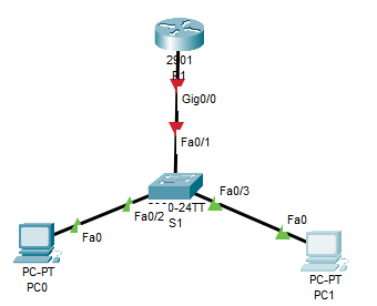
其中Fa0/2在VLAN10下,Fa0/3在VLAN20下
配置
交换机配置
创建VLAN
S1(config)#vlan 10
S1(config-vlan)#vlan 20
S1(config-vlan)#exit
配置Fa0/1为中继端口
S1(config)#interface f0/1
S1(config-if)#switchport mode trunk
S1(config-if)#exit
配置Fa0/2与Fa0/3为接入模式,并设置VLAN
S1(config)#interface f0/2
S1(config-if)#switchport mode access
S1(config-if)#switchport access vlan 10
S1(config-if)#exit
S1(config)#interface f0/3
S1(config-if)#switchport mode access
S1(config-if)#switchport access vlan 20
S1(config-if)#exit
路由器配置
路由器一个物理端口接收多个VLAN流量是通过分配子端口来进行的。
启用物理端口(这一步很重要,最好先激活父端口再配置子端口防止忘记)
R1(config)#interface g0/0
R1(config-if)#no shutdown
R1(config-if)#exit
配置子端口VLAN号,按802.1q格式封装,并分配ipv4地址。
子端口的命名规范为父端口名称.VLAN号 ,尽管VLAN号部分怎么写对最终效果没有影响,但是为了日后维护时能通过名字一眼就知道对应的VLAN,强烈建议按这种格式来
R1(config)#interface g0/0.10
R1(config-subif)#encapsulation dot1q 10
R1(config-subif)#ip address 172.17.10.1 255.255.255.0
R1(config-subif)#exit
R1(config)#interface g0/0.20
R1(config-subif)#encapsulation dot1q 20
R1(config-subif)#ip address 172.17.20.1 255.255.255.0
R1(config-subif)#exit
PC配置
对PC配置,无非就是设置一下IPv4地址和子网掩码以及默认网关
默认网关地址为所在VLAN下对应路由子端口的IPv4地址。
PC0的配置如下图所示
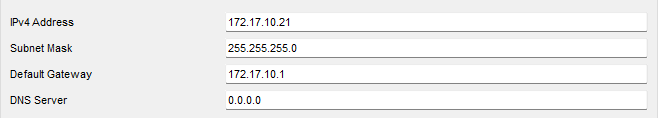
PC1的IPv4地址为172.17.20.23/24,默认网关为172.17.20.1,此处省略配置步骤
验证
检验VLAN
S1#show vlan该命令输出如下
VLAN Name                             Status    Ports
---- -------------------------------- --------- -------------------------------
1    default                          active    Fa0/4, Fa0/5, Fa0/6, Fa0/7
                                                Fa0/8, Fa0/9, Fa0/10, Fa0/11
                                                Fa0/12, Fa0/13, Fa0/14, Fa0/15
                                                Fa0/16, Fa0/17, Fa0/18, Fa0/19
                                                Fa0/20, Fa0/21, Fa0/22, Fa0/23
                                                Fa0/24, Gig0/1, Gig0/2
10   VLAN0010                         active    Fa0/2
20   VLAN0020                         active    Fa0/3
1002 fddi-default                     active
1003 token-ring-default               active
1004 fddinet-default                  active
1005 trnet-default                    active

VLAN Type  SAID       MTU   Parent RingNo BridgeNo Stp  BrdgMode Trans1 Trans2
---- ----- ---------- ----- ------ ------ -------- ---- -------- ------ ------
1    enet  100001     1500  -      -      -        -    -        0      0
10   enet  100010     1500  -      -      -        -    -        0      0
20   enet  100020     1500  -      -      -        -    -        0      0
1002 fddi  101002     1500  -      -      -        -    -        0      0
1003 tr    101003     1500  -      -      -        -    -        0      0
检验路由表
R1#show ip route | begin Gateway输出结果:
Gateway of last resort is not set

     172.17.0.0/16 is variably subnetted, 4 subnets, 2 masks
C       172.17.10.0/24 is directly connected, GigabitEthernet0/0.10
L       172.17.10.1/32 is directly connected, GigabitEthernet0/0.10
C       172.17.20.0/24 is directly connected, GigabitEthernet0/0.20
L       172.17.20.1/32 is directly connected, GigabitEthernet0/0.20
Ping测试
PC0终端ping默认网关
C:\>ping 172.17.10.1PC0终端ping PC2
C:\>ping 172.17.20.23成功的话会有Replay from xxx.xxx.xxx.xxx bytes = xx time<xms TTL=xxx格式的字样
Tracert测试
同样在PC0终端键入如下命令
C:\>tracert 172.17.20.23结果如下
Tracing route to 172.17.20.23 over a maximum of 30 hops:

  1   0 ms      0 ms      0 ms      172.17.10.1
  2   0 ms      0 ms      0 ms      172.17.20.23

Trace complete.